Editor’s Note: This manual is shared by Pellizzoni, a friend of MaXpeedingRods. The instruction is restricted to the assembly of MaXpeedingRods connecting rods on a Peugeot EW10J4 engine. However, the conrods are for the TU5JP4 engine. He milled the conrods and recorded all the works he did to mount the conrods when he realized that they didn’t fit.
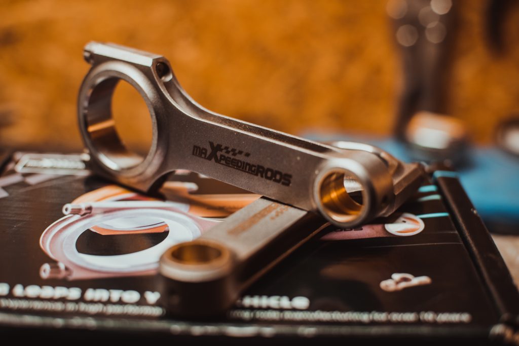
Complete tools and skills are suggested for the smooth running of the site. The assembly should be done in a clean place away from dust and humidity.
Preliminary machining of the connecting rods is needed in order to be able to mount these connecting rods on the engine. Ream the bronze ring (see photo below) to pass over a diameter of 21.00 (-0.005 / -0.02) mm so that the axis can be mounted tightly on the connecting rods.
It is also needed to machine the thickness of the small end because it is 20mm and it must be brought back to the dimension of 17mm, being careful to remove the same amount of material from each side of the connecting rods so that it stays centered.
After removing all of the engine peripherals to have access to the crankshaft, remove the cylinder head from the engine block. Loosen the connecting rods screws in order to extract the connecting rods caps.
Push on the connecting rods towards the top of the engine. Extract the piston / connecting rods assembly from the top of the engine.
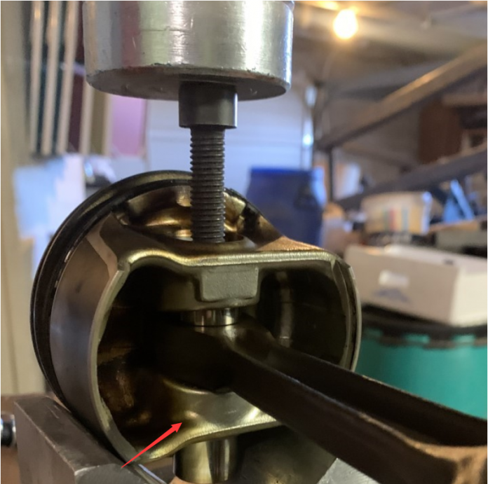
Then you have to extract the connecting rods shaft for this you will need a press and the material type shims, V and axis. If there is any difficulty in extracting the axle, try to heat the end of the connecting rod with the wing of a torch (see red arrow).

After having separated the connecting rods from the original piston, it is time to assemble the MaXpeedingRods connecting rods.
In order to facilitate the assembly of the axis in the connecting rods, it is better to place them in the freezer for 3-4 hours so that they can retract. Conversely, heat is needed – either using a heat gun or a cooking plate – the connecting rods to a temperature between 90-110 °C which will expand the bore.
CAUTION: Do not overheat the connecting rods as there is a risk of significant deformation which will render them unusable. OXYGEN / ACETYLENE TORCH IS PROHIBITED.
It will also be suggested to make a shim of 1 mm thickness in order to put the connecting rods correctly at the axis of the piston.
- Place the connecting rods horizontally and align the bores.
- Oil the bores with engine oil (NO DEGRIPPANT).
- Then slide the axis inside of the piston is of the connecting rods, if this one is a little hard to enter do not forcibly remove the axis and put it back in the freezer and check the alignment. You can use a mallet (NO HAMMER) to facilitate the insertion of the axle.
- When the piston / connecting rod assembly is assembled, check that the axis is free in the pistons.
- It is best to change the connecting rod bearings before reassembly on the crankshaft, as well as segmentation.
- Undo the connecting rods caps CAUTION each connecting rods has its matching cap, do not mix them. It is advisable to remove them one after the other.
- Insert the new bearings on the connecting rods.
- For assembly in the block, deposit a film of oil in the cylinders and insert the connecting rods from the top of the engine. The rings should be compressed to be able to insert the piston into the cylinder.
- Put a film of oil on the bearings.
- Replace the conrods cap and tighten the ARP2000 screws using a torque wrench.
At last, don’t forget the tighten procedures.
- Put the screws in contact.
- Make the first tightening to 12Nm.
- Make the final tightening to 65Nm.
Note: These assembly instructions are only indicative. The assembly of parts must be carried out by professionals. No claim can be made due to poor assembly.
